Written by: Franciszek Bartnik
This article describes an exemplary sensor circuit which can be integrated into the TreeDB. It is a more advanced version of the project used in the "Make your Day! Challenge 2015" mentioned in the previous article.
The circuit collects data using a Raspberry Pi 2 Model B and is build from the following components:
- 2 x DS18B20 digital temperature sensors
- 1x DHT22/AM2302 humidity sensor
- 1x MQ-2 gas sensor (for detecting smoke)
- 1x ADC0832 A/D converter chip
- 1x Raspberry Pi Camera Module
- 2x 10 kΩ resistors
- 1x Breadboard and wires
All of these(except the camera, which is connected directly to the raspberry pi) have been connected as seen below
For simplicity's sake, the red cable is always the power cable and the black is always the ground cable. All others are signal cables.
In the following paragraphs the traditional GPIO numbering system will be used, no the physical one.
The Thermometer Module
The thermometer module is the simplest of all modules. It is the one furthest to the right on the breadboard and consists of two DS18B20 sensors and one 10 kΩ resistor. There is also one more temperature sensor in the hygrometer, however will not concentrate on that one in this module.
The DS18B20 sensor has three pins:
- Left: Vcc (power input)
- Middle: Signal
- Right: Ground
In this circuit a voltage of 3.3V is applied across all sensors. Since the signal is already digital, we can connect the sensors directly to the raspberry pi, namely the GPIO 4 pin. We can connect both signal wires, since the system can distinguish between multiple signals at once. The 10kΩ resistor acts as a pull-up resistor for the signal, nothing more.
The Hygrometer Module
The hygrometer module is the one furthest to the left on the breadboard. It is also relatively simple.
The hygrometer is to be connected as following:

One of the pins is not used. As seen on the previous diagram, we also need a 10 kΩ pull-up resistor here. The signal wire is connected to GPIO 17.
The hygrometer also contains a temperature sensor, which can be accessed using the same signal wire as humidity.
The Smoke Detector Module
The smoke detector module utilizes the MQ-2 gas sensor as well as the ADC0832 Analog-to-Digital Converter. It is the most complicated of all modules. The gas sensor is to be connected as follows:
- Left: Ground
- Middle: Vcc
- Right: Signal
Since MQ-2 does not digitize the signal itself, we need to attach it to the ADC0832 A/D chip. It processes the analog signal into a format which the raspberry pi can read. The A/D converter is to be connected as follows:
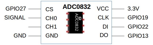
In the diagram on top, these wires represent the different pins:
- Blue: CLK (Clock)
- Grey: DI (Data In)
- Brown: DO (Data Out)
- Purple: CS (Channel Select)
- Pink: CH0 (Channel 0)
Conclusion
If connected correctly, the circuit described above can be used to collect data. Additionally to the modules described above, one can also use the camera(which is a separate module easily connected to the raspberry pi) and a built in thermometer for reading the CPU temperature.